
Waste to energy
Waste to energy
Waste to energy means the recovery of heat released during waste incineration to generate heat and electricity. The incineration plant uses mixed municipal waste as a fuel which cannot be otherwise used as a material, i.e. waste that is collected from black refuse bins and dumpsters and waste collected from industries.
Energy made from waste saves non-renewable raw materials such as coal and crude oil
- Once ignited, waste in the boiler incineration chamber burns without the need of any additional fuel.
- Ferrous and non-ferrous metals are separated from the incineration residues (slag) and then reused as a secondary raw material.
The waste to energy facility (ZEVO) guarantees minimum emissions emitted into the environment comparable with a heating plant or power station fuelled by natural gas and it is a pure source of energy to generate heat and electricity.
Advantages of the waste to energy facility
- recovery of thermal energy released in the incineration process to generate heat and elektricity
- primary non-renewable material and energy savings
- waste weight reduction to 28 % of the original values
- reduction in volume by 90 % of the original values, which means tenfold extension of the landfill site service life
- simple and efficient incineration process control
- perfect waste burnout down to inorganic inert material – slag
- slag contains a minimal quantity of organic residues (1–5 %)
- efficient separation of monitored pollutants from flue gases to values that meet statutory standards
- separation of ferromagnetic and non-ferromagnetic metals from slaguse of slag in the building industry
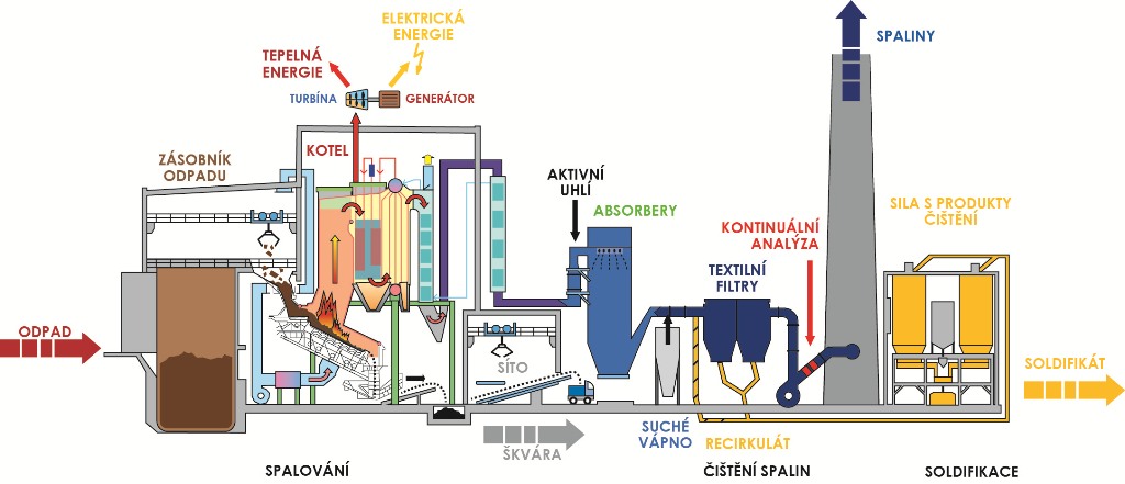
Technological process
The waste to energy facility ensures inertisation of biodegradable waste and it is also an important source of energy as it operates as a heating plant and power station. However, unlike these sources, it does not utilise primary non-renewable materials and energies to produce steam and electricity. The generated steam covers part of heat demand in Brno.
Incinerated waste path
Weighing system
The weighing system is the inlet point for trucks of all suppliers and consumers of waste and raw materials. Weighing is automatic and the data is processed by a special software programme. On arriving at the incineration plant, the trucks bringing in waste pass through a detection system that can detect ionisation radiation. The weighing system keeps records of inputs and outputs to/from the waste to energy facility. This is where the waste path is divided into the path for waste intended for energy recovery and path of separately collected waste intended for final sorting at the post—sorting line.
Waste bunker
Once weighed, the truck with combustible waste heads towards one of eight feeding gates. The operator checks the declared waste and permits its emptying into the bunker. The crane operator uses a polyp grab to remove the fed-in waste from the inlet chutes of the waste bunker and crushing system chutes and moves the waste further into the bunker where the waste is homogenised, and feeds the waste into the hoppers of the individual boilers.
Boilers with accessories
The boiler room is fitted with two five-pass boilers with reverse grates type MARTIN, whose technical parameters and air mode ensure optimal operating conditions of the waste incineration process.
Waste neither fed to the boiler burns by itself and does nor need any additional fuel. Waste passes through the heating, drying, gasifying, burning and final burning stages on the grate. The temperature in the boiler incineration chamber is above 1000°C. The waste incineration product – slag- falls into a wet extractor. This is where the slag is extinguished and cooled and then transported through a vibration sorting system via a belt conveyer to the slag bunker.
Turbine
Superheated steam passes through a bleeder condensing steam turbine with high pressure and low pressure sections. High pressure superheated steam expands in the turbine and thermal energy and pressure energy are transformed into mechanical energy resulting in mechanical action through a bladed rotor drive. The rotor is connected to a gearbox and el. power generator transforming mechanical action into el. energy. Regulated as well as unregulated turbine takeoff ensures electricity generation as well as steam supply for the central distribution system of the city of Brno as well as for technological purposes.
Chemical water treatment (CHÚV)
Chemical water treatment ensures sufficient supplies of feeding water with the defined parameters for the entire boiler boiling system. The feeding water consists largely of return condensate coming from the CZT network, clean condensate from the air cooled condenser and water from chemical water treatment which mainly utilises drinking water for the treatment. Given the relatively high salt content in raw water, if untreated, the boiler boiling system would get clogged with mineral sediments and the turbine could be damaged and oxygen dissolved in water would strongly contribute to the boiler boiling system corrosion.
Flue gas treatment
An integral part of the waste incineration technological process is the five-stage flue gas treatment system.
- First flue gas treatment stage is installed directly in the boiler incineration chamber. Chemical reactions ensure significant reduction in the volume of nitrogen oxides in the flue gases.
- Second flue gas treatment stage is adsorption of heavy metals and persistent organic pollutants type PCDD/F, PCB and PAU.
- Third flue gas treatment stage consists in the spraying of finely disperse aqueous limy suspension in flue gas stream. Gaseous flue gases from the boilers are fed through flue ducts into absorbers where the flue gases are cleaned.
- Fourth flue gas treatment stage is installed in the flue duct between absorbers and textile filters and it is based on the dry lime method consisting in the addition of dry slack lime into the flue gases stream. This treatment starts automatically if the concentration of acid components in flue gases increases.
- Fifth flue gas treatment stage is textile filters used to separate all mechanical pollutants and solid reaction products from the flue gases. The end product of flue gas treatment consists of limy salts, fly ash, activated carbon and reagent excess. The entire flue gas treatment process is controlled automatically by a control system so as the output of the flue gas treatment system contains a residual content of monitored pollutants at a level below the permissible emission limits. The flue gas treatment efficiency with respect to the pollutants is at 99 %. Before entering the duct, the flue gases are continuously monitored and evaluated.
Slag management
Slag management is the end-of-pipe technological system treating slag - waste inert product of the incineration process. The technology is used to handle and separate slag, it consists of a slag bunker, traveller crane, conveyer system and separation line. After passing the combustion chamber, slag passes through a wet slag extractor and via belt conveyers it is transported to a concrete bunker. Sorted iron and aluminium are transported off site for further reuse as secondary raw materials. Slag is used to secure landfill sites. The company’s objective is to ensure such quality parameters of the slag to enable its use as building material (backfill, underfill) and thus minimise waste production.